Heritage · Shipbuilding
From mould loft to 3D.
Before software there was a floor. Ships were drawn full size in chalk, faired by eye, and carried to the plate as templates. The tools changed. The standard — fair lines, numbered parts, marks a builder can trust — did not.
Where the lines came from
het vak- The loft floor
Full size, in chalk
Hull lines were laid out at full scale in chalk on the mould loft floor — the mallenzolder. The ship existed there first, line by line, before any steel was cut.
- Fairing
Battens and ducks
Long wooden battens, held down by lead ducks, were sprung through the plotted points and eased until every curve ran fair. A line was right when the eye said so.
- Marking
Numbers, punch and chalk
Frames were numbered; erection marks were punched or chalked onto the plates. Hundreds of parts, and every one told where it belonged.
- Templates
The mal carries the shape
Templates — mallen — carried each shape from the loft floor to the plate. The template was the agreement between drawing and steel.
- Scale and light
Smaller floors, projected lines
Lofting moved to scale, one to ten, and optical projection put the drawn line back onto the plate at full size. Less floor, same discipline.
- 1960s–70s
Numbers cut the steel
Numerically-controlled cutting arrived in the shipyards. For the first time, a line did not have to be drawn on the plate to be cut from it.
- 1970s–80s
Lines from CAD
The lines themselves began to come from CAD. The loft floor’s geometry moved into the computer, and fairing became screen work.
- Today
The 3D product model
The 3D product model now carries what the loft floor once did: every frame, every seam, every mark. Work preparation is the craft of getting it onto the workshop floor — complete, numbered and checked.
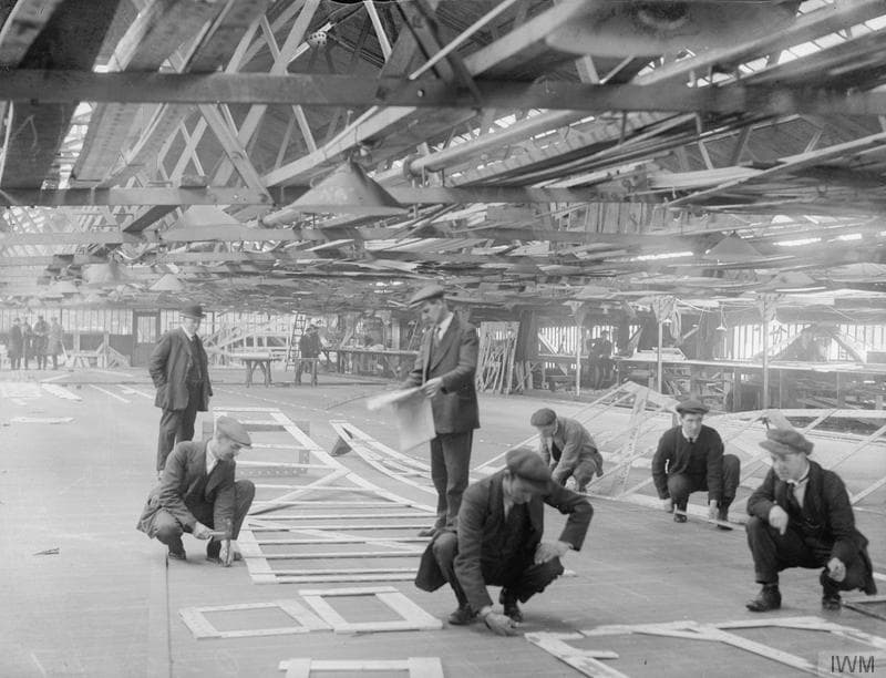
The moulding loft: hull lines drawn out full size on the floor. Tyne shipyard, 1914-1918.
Horace Nicholls · Imperial War Museums Q20027 · public domain
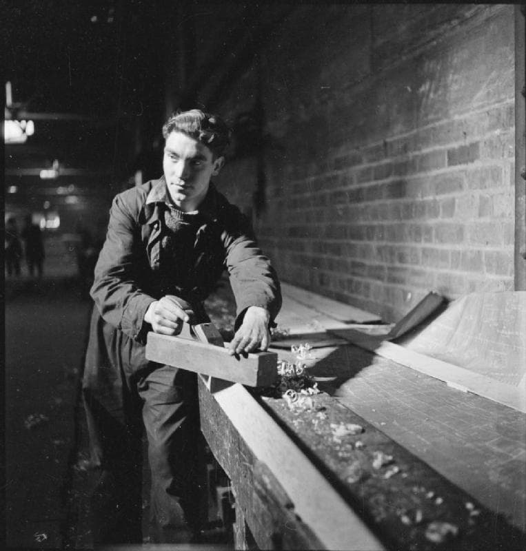
Template work in the mould loft — the shapes that walked from floor to plate. Britain, 1943.
Cecil Beaton · Imperial War Museums DB86 · public domain
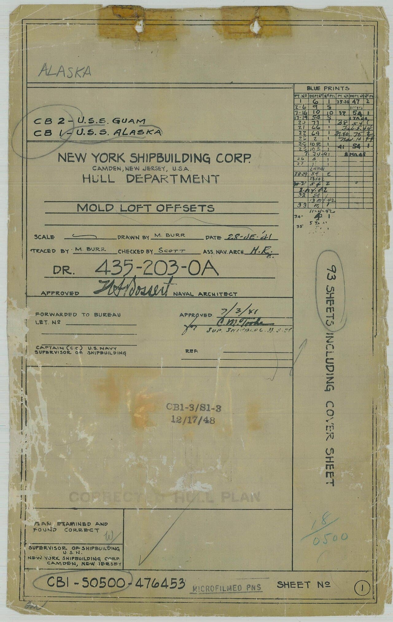
A mold-loft offsets booklet: the hull written as numbers, 1941 — the direct ancestor of today's 3D model.
US National Archives, 76605278 · public domain
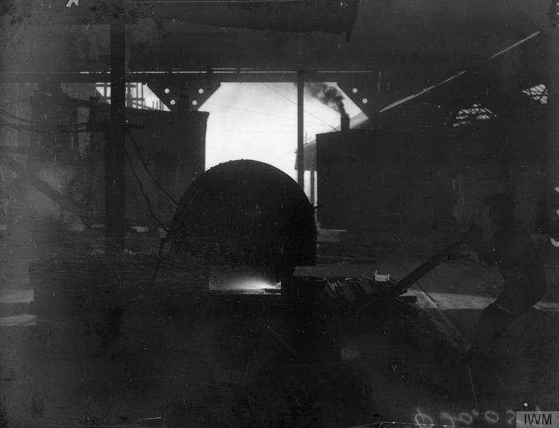
Cutting plate at the yard, 1914-1918 — marks and templates decided every cut.
Imperial War Museums Q20059 · public domain
The words that survived
werftaalSix terms from the loft floor, still in daily use. We use them the way the yard does.
The marks are older than the machines.
The centreline scribed on a plate today, the frame number, the waterline reference — they descend directly from loft-floor practice. The 3D model carries what the chalk once carried.
Tekwork prepares building packages in that tradition: every part numbered, every file checked, every delivery certified. A complete fabrication package, not a folder of loose files.